// the display: clock, weather, stocks, Spotify now-playing, Todoist tasks
Why I built it
I wanted a summer project that pushed beyond what I'd learned in embedded systems while giving me something useful for my apartment. Instead of buying a desk display, I decided to design and build one from scratch.
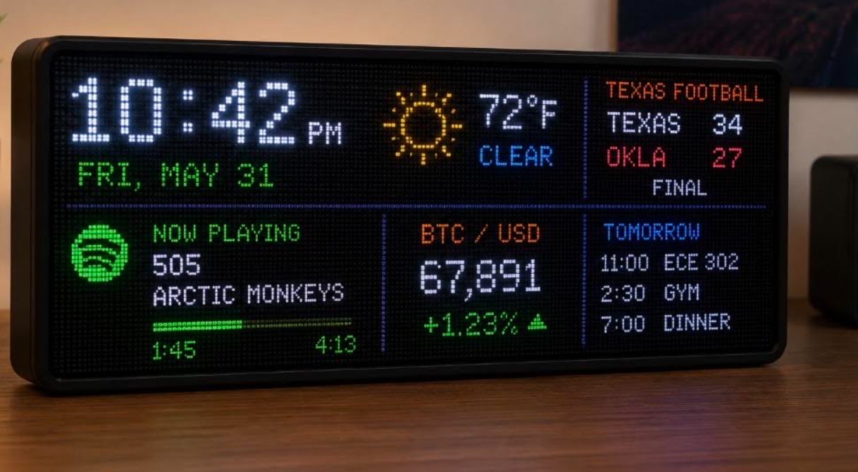
// the AI concept render I started from: the target I was building toward
What it is
A Wi-Fi-connected 128×32 RGB LED dashboard that displays the information I'd otherwise reach for my phone to check:
- Spotify now-playing: album-synced info with scrolling track/artist text and a live progress bar
- Weather (Open-Meteo): icon, temperature, condition
- Todoist tasks with due dates, scrolling
- Stock quotes (Finnhub): price change with up/down arrows
- Clock + date, NTP-synced with automatic DST
- Idle mode: a custom animated aurora with a twinkling starfield when nothing is playing
Architecture
The core engineering challenge: HUB75 panels have no memory. The MCU must continuously scan pixel data to the panels, so the render loop can never be blocked by a slow network call. The design splits work across the ESP32's two cores:
- spotifyTaskevery 5 s
- weatherTaskevery 10 min
- todoTaskevery 60 s
- stockTaskevery 60 s
shared state
- clock / date zone
- weather zone
- Spotify zoneprogress + scroll
- tasks / stocks zone
- aurora idle screen
Each API gets its own FreeRTOS task pinned to core 0. Shared state uses two mutexes: one for data, one for HTTP, because the TLS client can't handle concurrent requests. Rendering is dirty-region based: each zone repaints only when its data changes, minimizing SPI traffic and eliminating flicker.
A desk gadget that needs daily reboots is a failed desk gadget. To make the system resilient, I added a self-healing watchdog stack: Wi-Fi auto-reconnect, stale TLS connection reset, and a full ESP.restart() if no network call has succeeded in 15 minutes.
How it came together
PHASE 1Bringing the panels to life
Wired the ESP32 to one HUB75 panel on jumpers, got the DMA driver scanning, drew the first pixels. Then chained the second panel into a single 128×32 canvas.
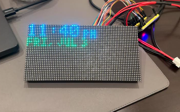
// first light on panel one
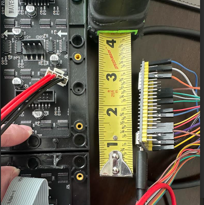
// the hand-wired ESP32 harness: every one of these jumpers later became a PCB trace
PHASE 2Wi-Fi + first API
Network stack up, NTP clock synced, then Open-Meteo weather as the first live data on glass.
PHASE 3Going concurrent
More APIs meant blocking calls stalling the render loop: restructured into one FreeRTOS task per API on core 0, mutex-guarded shared state, render loop alone on core 1.
PHASE 4Spotify + polish
OAuth refresh-token flow, scrolling track text, live progress bar. Built the aurora + starfield idle animation for when nothing's playing.
PHASE 5Making it survive
A desk gadget that needs reboots is a failed desk gadget: layered in Wi-Fi reconnect, stale-TLS reset, and a 15-minute dead-man restart.
PHASE 6Real hardware
Power and signal problems (below) pushed the project off jumper wires: designed the PCB in KiCad and sent it to fab.
The hard parts
Sagging supply rails
Bright full-white frames browned out the panels, the supply couldn't hold 5V under peak current draw. Diagnosed the sag, learned to budget for worst-case (not typical) panel current, and resized the power path.
Burned-out barrel connector
The stock barrel connector quietly cooked itself carrying sustained panel current. Lesson learned about connector current ratings; replaced with screw terminals sized for the job, a decision carried into the PCB design.
Signal integrity
Random glitched pixels traced back to the rat's nest of jumpers carrying fast HUB75 clock and data lines. Shortening and re-routing helped; the real fix was designing a proper board.
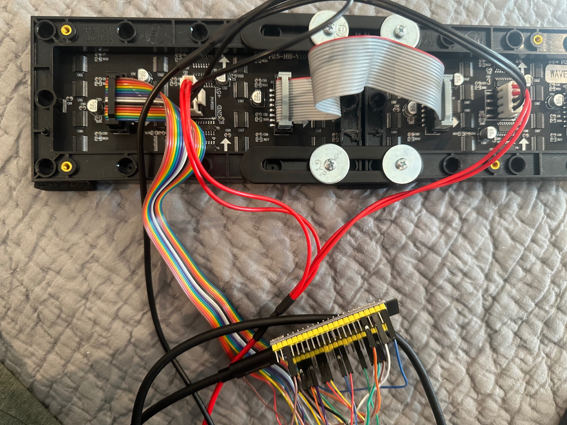
// the prototype wiring that motivated the PCB. every embedded engineer has this photo.
The PCB
Designed in KiCad and fabricated by JLCPCB, the custom PCB integrates ESP32 socket headers, a HUB75 output header, screw-terminal power input with bulk decoupling, a optional barrel-jack, and 17 labeled test points to simplify bring-up and debugging.
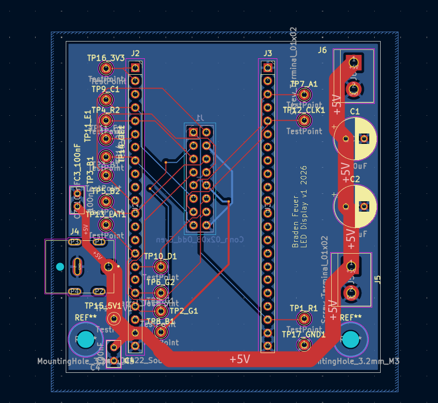
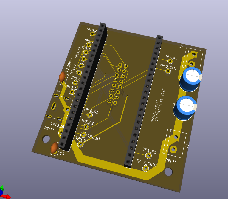
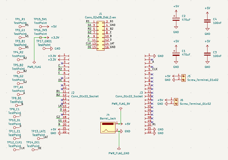
// layout, 3D render, and schematic. board is in transit from the fab, assembly photos coming.